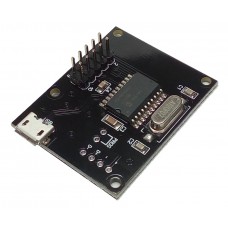
The JC24 is a small and simple joystick controller that can be used to build your own buttons box or add push buttons or rotary encoders to your existing wheel or dashboard.
Characteristics
- The JC24 joystick controller is very compact in size and measures only 45mm x 37mm.
- It is powered through the USB port and doesn’t require an external power supply.
- Up to 24 push buttons or 12 rotary encoders can be connected.
How to connect buttons to the JC24 Joystick Controller
- Buttons are connected as a 4×6 matrix, like in the picture above.
- Each pin of a button connects to a COLUMN pin or to a ROW pin of the joystick controller.
- Diodes are NOT required if you only connect push buttons, but not rotary encoders.
How to connect rotary encoders to the JC24 Joystick Controller
Rotary Encoders are special devices with 3 pins. Each rotary encoder replaces 2 buttons: when the encoder is rotated clockwise a press of one of the buttons is simulated. When the rotary encoder is rotated anti-clockwise, a press of the other button is simulated.
Rotary Encoders are connected to the JC24 joystick controller similarly to the picture above:
- The central pin of the rotary encoder connects to one of the ROW pins. In the picture above the central pins are connected to ROW 1.
- The other two pins of the rotary encoder connect to COLUMNS 1 and 2, or to COLUMNS 3 and 4.
- Diodes are often necessary when using rotary encoders but now always. See below when diodes are required.
- When a new rotary encoder is connected to the JC24 Joystick Controller, use the Configuration utility to configure the digital inputs of the controller to work with the rotary encoder. More details are available below.
- In the picture above the first rotary encoder replaces Buttons 1 & 2. The second rotary replaces Buttons 3 & 4.
When are diodes required?
Diodes are NOT required in any of the following cases:
- Only push buttons are used (no rotary encoders).
- If rotary encoders are being used,they are connected to only ONE ROW of the input matrix. All the other 5 rows are not used. If you have connected push buttons as well, push buttons and rotary encoders are connected to the same ROW of inputs and the other 5 rows are unused.
In all the other cases, diodes must be connected between the pins of the rotary encoders (and push buttons) and the COLUMN pins of the JC24 joystick controller, like in the picture above.
Configuring the JC24 Joystick Controller
The Configuration Tool for the JC24 Joystick Controller, which is available in the Download Area of the website, is used to configure which digital inputs of the controller are connected to rotary encoders or push buttons. You can also configure the polling interval.
In the section marked with 1 in the picture above, set the checkbox if the corresponding inputs are connected to a rotary encoders.
The polling interval (marked with 2) determines how often the inputs of the controllers are read. The default value is 20 ms, which is usually fine if you are only using push buttons. The reason why you don’t want to read the state of the buttons too quickly is because when a button is pushed, its contacts normally bounce for some milliseconds and if these bounces are read by the microcontroller more button pushes would be reported. Instead, reading the state of the buttons every 20ms should guarantee that the bouncing has stopped between readings. If you are using rotary encoders, 20ms between one reading and the following one could be too long if you rotate the encoder very quickly. In that case the polling interval can be reduced to 15ms, 10ms or 5ms.
Custom Firmware
If you would like to integrate the JC24 Joystick Controller into your products, like button boxes, wheels… a custom version of the firmware that displays the names of your company and of your product can be made available. This is a free service but a minimum quantity order might be required.
JC24 Joystick Controller
- Product Code: JC24 Joystick Controller
-
£18.00
Available Options
Related Products
Rotary Encoder
CTS Electronic Components 288T232R161A2 rotary encoder.Includes black plastic knob.Detent Points:&nb..
£4.80


